

Это старая версия документа!

Процессорный модуль NMS-SM-RK3568 выполнен на основе процессора производства Rockchip RK3568, который оснащен двухъядерным графическим процессором и высокопроизводительным NPU, поддерживающим до 8 ГБ ОЗУ.
Имея различные интерфейсы ввода и вывода видео, он подходит для таких сценариев, как интеллектуальный сетевой видеорегистратор, облачный терминал, шлюз IoT и промышленное управление.
| Внешние разъемы | Краевой разъём в соответствии со SMARC, по стандарту (2.0\2.1) |
|---|---|
| Процессор | RK3568 |
| Ядра:4х-ядерный 64х-битный Cortex-A55, 22нм техпроцесс, частота до 2.0ГГц | |
| Графический ускоритель: ARM G52 2EE, поддержка OpenGL ES 1.1/2.0/3.2, OpenCL 2.0, Vulkan 1.1 | |
| Видеоускоритель: аппаратное декодирование 4K 60к/с H.265/H.264/VP9, аппаратное кодирование 1080P 100к/с H.265/H.264, 8M ISP, HDR | |
| Нейросопроцессор: 0.8Tops@INT8, интегрированнный высокопроизводительный AI ускоритель RKNN NPU, поддержка Caffe/TensorFlow/TFLite/ONNX/PyTorch/Keras/Darknet | |
| ОЗУ | Память LPDDR4 2 ГБайт (512M x 32) (MT53D512M32D2DS-053WT:D) |
| Флэш-память | Память eMMC 16 ГБайт (THGAMRG7T13BAIL) |
| ИС управления питанием | PMIC (RK809-5) |
| Прочие компоненты | Часы реального времени RTC (PCF8523TK) |
| 2x Гигабит ETH PHY (BCM54210PEB1IMLG) | |
| PCIe CLK GEN 25 MHz XTAL→4x 100MHz (PI6CG18401Z) | |
| Переключатель SATA → USB3 1:2 (CBTL02043A ) | |
| Интерфейсы | 1x USB 2.0 |
| 1x USB 3.0 OTG | |
| 1x USB SS | |
| 1x PCIe 2.1 | |
| 2x PCIe 3.0 | |
| 2x CAN | |
| 3x UART + 1x отладочный UART | |
| 2x SPI | |
| 3x I2C | |
| 1x I2S | |
| 2x PWM | |
| 1x SATA | |
| 1x HDMI | |
| 1x eDP | |
| 1x MIPI DSI or LVDS | |
| 1x SDIO | |
| 2x ETH 1GB | |
| 20x GPIO | |
| Напряжение питания | +5 Вольт |
| Потребление | TBD |
| Габаритные размеры | 82×50 мм |
| Название документа | Краткое описание | Версия | Дата |
|---|---|---|---|
| nms-sm-evm_v1_prod_sch.pdf | Схема электрическая принципиальная NMS-SM-EVM v1 | v1 | 2022.09.15 |
| nms-sm-rk3568_v1_prod.step | STEP-файл модуля NMS-SM-RK3568 v1 | v1 | 2022.10.07 |
Размер платы : 82 х 50 мм.
Печатная плата состоит из 8 слоев, часть из которых являются заземляющими для подавления помех.


| Позиционное обозначение | P/N | Описание |
|---|---|---|
| D1 | RK3568 | CPU |
| D2 | MT53D512M32D2DS-053WT:D | LPDDR4 |
| D3 | THGAMRG7T13BAIL | EMMC |
| D4, D5 | BCM54210PEB1IMLG | ETH PHY |
| D7 | RK809-5 | PMIC |
| D9 | FAN53200UC35X | DCDC BUCK |
| D12 | PI6CG18401ZHIEX | PCIe CLK GEN |
| D13 | NCP1597BMNTWG | DCDC buck |

| Позиционное обозначение | P/N | Описание |
|---|---|---|
| D6 | CBTL02043ABQ.115 | SATA →USB3 1:2 SW |
| D11 | PCF8523TK/1.118 | RTC |
| D14, D15 | NLSV2T244MUTAG | LOGIC BUF |
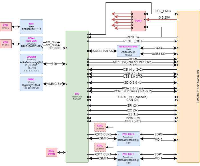
На рисунке 5 показаны функциональные модули в процессорной системе RK3568.

На плате NMS-SM-RK3568 доступно три внешних интерфейса I2C и два внутренних для взаимосвязи процессора и периферийных устройств.
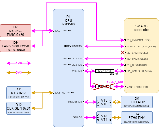
| Устройство | Адрес |
|---|---|
| PMIC | 0x00110000 |
| DCDC CONV | 0x01100000 |
| Устройство | Адрес |
|---|---|
| RTC | 0x01101000 |
| CLK GEN | 0x01100001 |

На нижней стороне платы разъемы отсутствуют.
Распиновка разъема X1 согласно SMARC
| Pin # | Name STANDART | Signals_SM_RK3568 | Group | I/O Type | I/O Level | PU / PD SM_RK3568 | Description | Power Domain | Comments |
|---|---|---|---|---|---|---|---|---|---|
| P1 | SMB_ALERT# | NC | MANAGEMENT | I OD CMOS | 1V8…5V | SMBus Alert# (Interrupt) Signal | Standby/Sleep | ||
| P2 | GND | GND | PWR GND | ||||||
| P3 | CSI1_CK+ | MIPI_CSI.CLK0._P | CSI1 | I D-PHY | CSI1 differential clock input (point to point) | Runtime | |||
| P4 | CSI1_CK- | MIPI_CSI.CLK0._N | CSI1 | I D-PHY | CSI1 differential clock input (point to point) | Runtime | |||
| P5 | GBE1_SDP | ETH1.SDP | GBE1 | I/O CMOS | 3V3 | IEEE 1588 Trigger Signal for Hardware Implementation of PTP (Precision Time Protocol) | Standby | ||
| P6 | GBE0_SDP | ETH0.SDP | GBE0 | I/O CMOS | 3V3 | IEEE 1588 Trigger Signal for Hardware Implementation of PTP (Precision Time Protocol) | Standby | ||
| P7 | CSI1_RX0+ | MIPI_CSI.0._P | CSI1 | I D-PHY / I M-PHY | CSI1 differential input (point to point) | Runtime | |||
| P8 | CSI1_RX0- | MIPI_CSI.0._N | CSI1 | I D-PHY / I M-PHY | CSI1 differential input (point to point) | Runtime | |||
| P9 | GND | GND | PWR GND | ||||||
| P10 | CSI1_RX1+ | MIPI_CSI.1._P | CSI1 | I D-PHY / I M-PHY | CSI1 differential input (point to point) | Runtime | |||
| P11 | CSI1_RX1- | MIPI_CSI.1._N | CSI1 | I D-PHY / I M-PHY | CSI1 differential input (point to point) | Runtime | |||
| P12 | GND | GND | PWR GND | ||||||
| P13 | CSI1_RX2+ | NC | CSI1 | I D-PHY / I M-PHY | CSI1 differential input (point to point) | Runtime | |||
| P14 | CSI1_RX2- | NC | CSI1 | I D-PHY / I M-PHY | CSI1 differential input (point to point) | Runtime | |||
| P15 | GND | GND | PWR GND | ||||||
| P16 | CSI1_RX3+ | NC | CSI1 | I D-PHY / I M-PHY | CSI1 differential input (point to point) | Runtime | |||
| P17 | CSI1_RX3- | NC | CSI1 | I D-PHY / I M-PHY | CSI1 differential input (point to point) | Runtime | |||
| P18 | GND | GND | PWR GND | ||||||
| P19 | GBE0_MDI3- | ETH0.MDI3._N | GBE0 | I/O GBE MDI | Differential Pair Signals for External Transformer | Standby | |||
| P20 | GBE0_MDI3+ | ETH0.MDI3._P | GBE0 | I/O GBE MDI | Differential Pair Signals for External Transformer | Standby | |||
| P21 | GBE0_LINK100# | ETH0.LED_100# | GBE0 | O OD CMOS | 3V3 | Link Speed Indication LED for GBE0 100Mbps | Standby | Shall be able to sink 24mA or more Carrier LED current. | |
| P22 | GBE0_LINK1000# | ETH0.LED_1000# | GBE0 | O OD CMOS | 3V3 | Link Speed Indication LED for GBE0 1000Mbps | Standby | Shall be able to sink 24mA or more Carrier LED current. | |
| P23 | GBE0_MDI2- | ETH0.MDI2._N | GBE0 | I/O GBE MDI | Differential Pair Signals for External Transformer | Standby | |||
| P24 | GBE0_MDI2+ | ETH0.MDI2._P | GBE0 | I/O GBE MDI | Differential Pair Signals for External Transformer | Standby | |||
| P25 | GBE0_LINK_ACT# | ETH0.LED_ACT# | GBE0 | O OD CMOS | 3V3 | Link / Activity Indication LED Driven Low on Link (10, 100 or 1000 Mbps) Blinks on Activity | Standby | Shall be able to sink 24mA or more Carrier LED current. | |
| P26 | GBE0_MDI1- | ETH0.MDI1._N | GBE0 | I/O GBE MDI | Differential Pair Signals for External Transformer | Standby | |||
| P27 | GBE0_MDI1+ | ETH0.MDI1._P | GBE0 | I/O GBE MDI | Differential Pair Signals for External Transformer | Standby | |||
| P28 | GBE0_CTREF | NC | GBE0 | Analog | 0…3V3 | Center-Tap Reference Voltage for Carrier Board Ethernet Magnetic (if required by the Module GBE PHY) | Standby | ||
| P29 | GBE0_MDI0- | ETH0.MDI0._N | GBE0 | I/O GBE MDI | Differential Pair Signals for External Transformer | Standby | |||
| P30 | GBE0_MDI0+ | ETH0.MDI0._P | GBE0 | I/O GBE MDI | Differential Pair Signals for External Transformer | Standby | |||
| P31 | SPI0_CS1# | SPI0.CS1 | SPI0 | O CMOS | 1V8 | SPI0 Master Chip Select 1 | Standby | ||
| P32 | GND | GND | PWR GND | ||||||
| P33 | SDIO_WP | SDIO_WP | SDIO | I OD CMOS | 1V8 or 3V3 | PU 10K | SDIO Write Protect. This signal denotes the state of the write-protect tab on SD cards. | Runtime | |
| P34 | SDIO_CMD | SDMMC0.CMD | SDIO | I/O CMOS | 1V8 or 3V3 | SDIO Command/Response. This signal is used for card initialization and for command transfers. During initialization mode this signal is open drain. During command transfer this signal is in push-pull mode. | Runtime | ||
| P35 | SDIO_CD# | SDIO_CD# | SDIO | I OD CMOS | 1V8 or 3V3 | PU 10K | SDIO Card Detect. This signal indicates when a SDIO/MMC card is present. | Runtime | |
| P36 | SDIO_CK | SDMMC0.CLK | SDIO | O CMOS | 1V8 or 3V3 | SDIO Clock. With each cycle of this signal a one-bit transfer on the command and each data line occurs. | Runtime | SDIO controller will detect SD Cards voltage level (1.8V for UHS-I and 3.3V for standard) and adjust its I/O voltage level accordingly | |
| P37 | SDIO_PWR_EN | SDIO_PWR_EN | SDIO | O CMOS | 3V3 | SDIO Power Enable. This signal is used to enable the power being supplied to a SD/MMC card device. | Runtime | Should be driven low in Standby Mode by the Module | |
| P38 | GND | GND | PWR GND | ||||||
| P39 | SDIO_D0 | SDMMC0.DATA.0 | SDIO | I/O CMOS | 1V8 or 3V3 | SDIO Data lines. These signals operate in push-pull mode. | Runtime | ||
| P40 | SDIO_D1 | SDMMC0.DATA.1 | SDIO | I/O CMOS | 1V8 or 3V3 | SDIO Data lines. These signals operate in push-pull mode. | Runtime | ||
| P41 | SDIO_D2 | SDMMC0.DATA.2 | SDIO | I/O CMOS | 1V8 or 3V3 | SDIO Data lines. These signals operate in push-pull mode. | Runtime | ||
| P42 | SDIO_D3 | SDMMC0.DATA.3 | SDIO | I/O CMOS | 1V8 or 3V3 | SDIO Data lines. These signals operate in push-pull mode. | Runtime | ||
| P43 | SPI0_CS0# | SPI0.CS0 | SPI0 | O CMOS | 1V8 | SPI0 Master Chip Select 0 | Standby | This signal can be used to select Carrier SPI as boot device | |
| P44 | SPI0_CK | SPI0.SCK | SPI0 | O CMOS | 1V8 | SPI0 Clock | Standby | ||
| P45 | SPI0_DIN | SPI0.MISO | SPI0 | I CMOS | 1V8 | SPI0 Master input / Slave output | Standby | also referred to as MISO | |
| P46 | SPI0_DO | SPI0.MOSI | SPI0 | O CMOS | 1V8 | SPI0 Master output / Slave input | Standby | also referred to as MOSI | |
| P47 | GND | GND | PWR GND | ||||||
| P48 | SATA_TX+ | SATA1.D_TX._P | SATA | O SATA | Serial ATA Channel 0 Transmit Output Differential Pair | Runtime | Series AC coupled on 10 nF Module | ||
| P49 | SATA_TX- | SATA1.D_TX._N | SATA | O SATA | Serial ATA Channel 0 Transmit Output Differential Pair | Runtime | Series AC coupled on 10 nF Module | ||
| P50 | GND | GND | PWR GND | ||||||
| P51 | SATA_RX+ | SATA1.D_RX._P | SATA | I SATA | Serial ATA Channel 0 Receive Input Differential Pair | Runtime | Series AC coupled on 10 nF Module | ||
| P52 | SATA_RX- | SATA1.D_RX._N | SATA | I SATA | Serial ATA Channel 0 Receive Input Differential Pair | Runtime | Series AC coupled on 10 nF Module | ||
| P53 | GND | GND | PWR GND | ||||||
| P54 | ESPI_CS0# / SPI1_CS0# / QSPI_CS0# | SPI1.CS0 | SPI1 | O CMOS | 1V8 | SPI1 Master Chip Select 0 | Standby | ||
| P55 | ESPI_CS1# / SPI1_CS1# / QSPI_CS1# | SPI1.CS1 | SPI1 | O CMOS | 1V8 | SPI1 Master Chip Select 1 | Standby | ||
| P56 | ESPI_CK / SPI1_CK / QSPI_CK | SPI1.SCK | SPI1 | O CMOS | 1V8 | SPI1 Clock | Standby | ||
| P57 | ESPI_IO_1 / SPI1_DIN / QSPI_IO_1 | SPI1.MISO | SPI1 | I CMOS | 1V8 | SPI1 Master input / Slave output | Standby | also referred to as MISO | |
| P58 | ESPI_IO_0 / SPI1_DO / QSPI_IO_0 | SPI1.MOSI | SPI1 | O CMOS | 1V8 | SPI1 Master output / Slave input | Standby | also referred to as MOSI | |
| P59 | GND | GND | PWR GND | ||||||
| P60 | USB0+ | USB2_HOST2._P | USB0 | I/O USB | USB | USB Differential Data Pairs for Port 0 | Standby | ||
| P61 | USB0- | USB2_HOST2._N | USB0 | I/O USB | USB | USB Differential Data Pairs for Port 0 | Standby | ||
| P62 | USB0_EN_OC# | USB2_HOST2_EN_OC# | USB0 | I/O OD CMOS | 3V3 | PU 10K | USB Over-Current Sense for Port 0 | Standby | Pulled low by Module OD driver to disable USB0 power. Pulled low by Carrier OD driver to indicate overcurrent situation. |
| P63 | USB0_VBUS_DET | NC | USB0 | I USB VBUS 5V | USB VBUS 5V | USB Port 0 Host Power Detection | Standby | ||
| P64 | USB0_OTG_ID | NC | USB0 | Input Pin to Announce OTG Device Insertion on USB 2.0 Port | Standby | ||||
| P65 | USB1+ | USB2_HOST3._P | USB1 | I/O USB | USB | USB Differential Data Pairs for Port 1 | Standby | ||
| P66 | USB1- | USB2_HOST3._N | USB1 | I/O USB | USB | USB Differential Data Pairs for Port 1 | Standby | ||
| P67 | USB1_EN_OC# | USB2_HOST3_EN_OC# | USB1 | I/O OD CMOS | 3V3 | PU 10K | USB Over-Current Sense for Port 1 | Standby | Pulled low by Module OD driver to disable USB1 power. Pulled low by Carrier OD driver to indicate overcurrent situation. |
| P68 | GND | GND | PWR GND | ||||||
| P69 | USB2+ | USB3_HOST1._P | USB2 | I/O USB | USB | USB Differential Data Pairs for Port 2 | Standby | ||
| P70 | USB2- | USB3_HOST1._N | USB2 | I/O USB | USB | USB Differential Data Pairs for Port 2 | Standby | ||
| P71 | USB2_EN_OC# | USB3_HOST1_EN_OC# | USB2 | I/O OD CMOS | 3V3 | PU 10K | USB Over-Current Sense for Port 2 | Standby | Pulled low by Module OD driver to disable USB2 power. Pulled low by Carrier OD driver to indicate overcurrent situation. |
| P72 | RSVD | rsvd | |||||||
| P73 | RSVD | rsvd | |||||||
| P74 | USB3_EN_OC# | USB3_OTG0_EN_OC# | USB3 | I/O OD CMOS | 3V3 | PU 10K | USB Over-Current Sense for Port 3 | Standby | Pulled low by Module OD driver to disable USB3 power. Pulled low by Carrier OD driver to indicate overcurrent situation. |
| P75 | PCIE_A_RST# | PCIE_A_RST# | PCIEA | O CMOS | 3V3 | PCIe Port A reset output | Runtime | ||
| P76 | USB4_EN_OC# | NC | USB4 | I/O OD CMOS | 3V3 | USB Over-Current Sense for Port 4 | Standby | Pulled low by Module OD driver to disable USB4 power. Pulled low by Carrier OD driver to indicate overcurrent situation. |
|
| P77 | PCIE_B_CKREQ# | PCIE_B_CKREQ# | PCIEB | IO OD CMOS | 3V3 | PU 10K | PCIe Port B clock request | Runtime | |
| P78 | PCIE_A_CKREQ# | PCIE_A_CKREQ# | PCIEA | IO OD CMOS | 3V3 | PU 10K | PCIe Port A clock request | Runtime | |
| P79 | GND | GND | PWR GND | ||||||
| P80 | PCIE_C_REFCK+ | PCIE20_REFCLK._P | PCIEC | O PCIE | Differential PCIe Link C reference clock output | Runtime | |||
| P81 | PCIE_C_REFCK- | PCIE20_REFCLK._N | PCIEC | O PCIE | Differential PCIe Link C reference clock output | Runtime | |||
| P82 | GND | GND | PWR GND | ||||||
| P83 | PCIE_A_REFCK+ | PCIE30_REFCLKA._P | PCIEA | O PCIE | Differential PCIe Link A reference clock output | Runtime | |||
| P84 | PCIE_A_REFCK- | PCIE30_REFCLKA._N | PCIEA | O PCIE | Differential PCIe Link A reference clock output | Runtime | |||
| P85 | GND | GND | PWR GND | ||||||
| P86 | PCIE_A_RX+ | PCIE30_L0.D_RX._P | PCIEA | I PCIE | Differential PCIe link A receive data pair | Runtime | |||
| P87 | PCIE_A_RX- | PCIE30_L0.D_RX._N | PCIEA | I PCIE | Differential PCIe link A receive data pair | Runtime | |||
| P88 | GND | GND | PWR GND | ||||||
| P89 | PCIE_A_TX+ | PCIE30_L0.D_TX._P | PCIEA | O PCIE | Differential PCIe link A transmit data pair | Runtime | Series AC coupled on Module 75-265 nF depending on PCIe generation | ||
| P90 | PCIE_A_TX- | PCIE30_L0.D_TX._N | PCIEA | O PCIE | Differential PCIe link A transmit data pair | Runtime | Series AC coupled on Module 75-265 nF depending on PCIe generation | ||
| P91 | GND | GND | PWR GND | ||||||
| P92 | HDMI_D2+ / DP1_LANE0+ | HDMI_TX.D2._P | HDMI | O TMDS HDMI | HDMI Port, Differential Pair Data Lines | Runtime | |||
| P93 | HDMI_D2- / DP1_LANE0- | HDMI_TX.D2._N | HDMI | O TMDS HDMI | HDMI Port, Differential Pair Data Lines | Runtime | |||
| P94 | GND | GND | PWR GND | ||||||
| P95 | HDMI_D1+ / DP1_LANE1+ | HDMI_TX.D1._P | HDMI | O TMDS HDMI | HDMI Port, Differential Pair Data Lines | Runtime | |||
| P96 | HDMI_D1- / DP1_LANE1- | HDMI_TX.D1._N | HDMI | O TMDS HDMI | HDMI Port, Differential Pair Data Lines | Runtime | |||
| P97 | GND | GND | PWR GND | ||||||
| P98 | HDMI_D0+ / DP1_LANE2+ | HDMI_TX.D0._P | HDMI | O TMDS HDMI | HDMI Port, Differential Pair Data Lines | Runtime | |||
| P99 | HDMI_D0- / DP1_LANE2- | HDMI_TX.D0._N | HDMI | O TMDS HDMI | HDMI Port, Differential Pair Data Lines | Runtime | |||
| P100 | GND | GND | PWR GND | ||||||
| P101 | HDMI_CK+ / DP1_LANE3+ | HDMI_TX.CK._P | HDMI | O TMDS HDMI | HDMI Port, Differential Pair Clock Lines | Runtime | |||
| P102 | HDMI_CK- / DP1_LANE3- | HDMI_TX.CK._N | HDMI | O TMDS HDMI | HDMI Port, Differential Pair Clock Lines | Runtime | |||
| P103 | GND | GND | PWR GND | ||||||
| P104 | HDMI_HPD / DP1_HPD | HDMI_HPD | HDMI | I CMOS | 1V8 | PD 1M | HDMI Hot Plug Active High Detection Signal that Serves as an Interrupt Request | Runtime | |
| P105 | HDMI_CTRL_CK / DP1_AUX+ | HDMI_CTRL.SCL | HDMI | I/O OD CMOS | 1V8 | PU 100K | I2C_CLK Line Dedicated to HDMI | Runtime | |
| P106 | HDMI_CTRL_DAT / DP1_AUX- | HDMI_CTRL.SDA | HDMI | I/O OD CMOS | 1V8 | PU 100K | I2C_DAT Line Dedicated to HDMI | Runtime | |
| P107 | DP1_AUX_SEL | NC | DP1++_HDMI | I CMOS | 1V8 | Strapping Signal to Enable Either HDMI or DP Output | Runtime | 0 - DP 1 - HDMI |
|
| P108 | GPIO0 / CAM0_PWR# | GPIO.0 | GPIO | I/O CMOS | 1V8 | GPIO Pin 0 Preferred Output | Runtime | Shared with CAM0_PWR# | |
| P109 | GPIO1 / CAM1_PWR# | GPIO.1 | GPIO | I/O CMOS | 1V8 | GPIO Pin 1 Preferred Output | Runtime | Shared with CAM1_PWR# | |
| P110 | GPIO2 / CAM0_RST# | GPIO.2 | GPIO | I/O CMOS | 1V8 | GPIO Pin 2 Preferred Output | Runtime | Shared with CAM0_RST# | |
| P111 | GPIO3 / CAM1_RST# | GPIO.3 | GPIO | I/O CMOS | 1V8 | GPIO Pin 3 Preferred Output | Runtime | Shared with CAM1_RST# | |
| P112 | GPIO4 / HDA_RST# | GPIO.4 | GPIO | I/O CMOS | 1V8 | GPIO Pin 4 Preferred Output | Runtime | Shared with HDA_RST# | |
| P113 | GPIO5 / PWM_OUT | GPIO.5 | GPIO | I/O CMOS | 1V8 | GPIO Pin 5 Preferred Output | Runtime | Shared with PWM_OUT | |
| P114 | GPIO6 / TACHIN | GPIO.6 | GPIO | I/O CMOS | 1V8 | GPIO Pin 6 Preferred Output | Runtime | Shared with TACHIN | |
| P115 | GPIO7 | GPIO.7 | GPIO | I/O CMOS | 1V8 | GPIO Pin 7 Preferred Output | Runtime | ||
| P116 | GPIO8 | GPIO.8 | GPIO | I/O CMOS | 1V8 | GPIO Pin 8 Preferred Output | Runtime | ||
| P117 | GPIO9 | GPIO.9 | GPIO | I/O CMOS | 1V8 | GPIO Pin 9 Preferred Output | Runtime | ||
| P118 | GPIO10 | GPIO.10 | GPIO | I/O CMOS | 1V8 | GPIO Pin 10 Preferred Output | Runtime | ||
| P119 | GPIO11 | GPIO.11 | GPIO | I/O CMOS | 1V8 | GPIO Pin 11 Preferred Output | Runtime | ||
| P120 | GND | GND | PWR GND | ||||||
| P121 | I2C_PM_CK | I2C_PM.SCL | MANAGEMENT | I/O OD CMOS | 1V8 | PU 2K2 | Power management I2C bus CLK | Standby/Sleep | |
| P122 | I2C_PM_DAT | I2C_PM.SDA | MANAGEMENT | I/O OD CMOS | 1V8 | PU 2K2 | Power management I2C bus DATA | Standby/Sleep | |
| P123 | BOOT_SEL0# | BOOT.0 | BOOT | I OD CMOS | 1V8 | PU 10K | Input straps determine the Module boot device. | Standby | |
| P124 | BOOT_SEL1# | nс_BOOT.1 | BOOT | I OD CMOS | 1V8 | Input straps determine the Module boot device. | Standby | ||
| P125 | BOOT_SEL2# | nс_BOOT.2 | BOOT | I OD CMOS | 1V8 | Input straps determine the Module boot device. | Standby | ||
| P126 | RESET_OUT# | RESET_OUT# | MANAGEMENT | O CMOS | 1V8 | General purpose reset output to Carrier Board. | Standby | ||
| P127 | RESET_IN# | RESET_IN# | MANAGEMENT | I OD CMOS | 1V8…5V | PU 10K | Reset input from Carrier Board. Carrier drives low to force a Module reset, floats the line otherwise. This signal Shall be level triggered during bootup to allow to stop booting of the module. After bootup it May act as an edge triggered signal. | Standby | |
| P128 | POWER_BTN# | POWER_BTN# | MANAGEMENT | I OD CMOS | 1V8…5V | PU 10K | Power-button input from Carrier Board. Carrier to float the line in in-active state. Active low, level sensitive. Should be debounced on the Module. | Sleep | |
| P129 | SER0_TX | SER0.RXTX.TX | SER0 | O CMOS | 1V8 | Asynchronous Serial Data Output Port 0 | Runtime | ||
| P130 | SER0_RX | SER0.RXTX.RX | SER0 | I CMOS | 1V8 | PU 100K | Asynchronous Serial Data Input Port 0 | Runtime | |
| P131 | SER0_RTS# | SER0.RTS | SER0 | O CMOS | 1V8 | Request to Send Handshake Line for Port 0 | Runtime | ||
| P132 | SER0_CTS# | SER0.CTS | SER0 | I CMOS | 1V8 | PU 100K | Clear to Send Handshake Line for Port 0 | Runtime | |
| P133 | GND | GND | PWR GND | ||||||
| P134 | SER1_TX | SER1.TX | SER1 | O CMOS | 1V8 | Asynchronous Serial Data Output Port 1 | Runtime | ||
| P135 | SER1_RX | SER1.RX | SER1 | I CMOS | 1V8 | PU 100K | Asynchronous Serial Data Input Port 1 | Runtime | |
| P136 | SER2_TX | SER2.RXTX.TX | SER2 | O CMOS | 1V8 | Asynchronous Serial Data Output Port 2 | Runtime | ||
| P137 | SER2_RX | SER2.RXTX.RX | SER2 | I CMOS | 1V8 | PU 100K | Asynchronous Serial Data Input Port 2 | Runtime | |
| P138 | SER2_RTS# | SER2.RTS | SER2 | O CMOS | 1V8 | Request to Send Handshake Line for Port 2 | Runtime | ||
| P139 | SER2_CTS# | SER2.CTS | SER2 | I CMOS | 1V8 | Clear to Send Handshake Line for Port 2 | Runtime | ||
| P140 | SER3_TX | SER3.TX | SER3 | O CMOS | 1V8 | Asynchronous Serial Data Output Port 3 | Runtime | ||
| P141 | SER3_RX | SER3.RX | SER3 | I CMOS | 1V8 | PU 100K | Asynchronous Serial Data Input Port 3 | Runtime | |
| P142 | GND | GND | PWR GND | ||||||
| P143 | CAN0_TX | CAN0.TX | CAN0 | O CMOS | 1V8 | CAN Port 0 Transmit Output | Runtime | ||
| P144 | CAN0_RX | CAN0.RX | CAN0 | I CMOS | 1V8 | CAN Port 0 Receive Input | Runtime | ||
| P145 | CAN1_TX | CAN1.TX | CAN1 | O CMOS | 1V8 | CAN Port 1 Transmit Output | Runtime | ||
| P146 | CAN1_RX | CAN1.RX | CAN1 | I CMOS | 1V8 | CAN Port1 Receive Input | Runtime | ||
| P147 | VDD_IN | VDD_IN | PWR | 3V…5.25V | |||||
| P148 | VDD_IN | VDD_IN | PWR | 3V…5.25V | |||||
| P149 | VDD_IN | VDD_IN | PWR | 3V…5.25V | |||||
| P150 | VDD_IN | VDD_IN | PWR | 3V…5.25V | |||||
| P151 | VDD_IN | VDD_IN | PWR | 3V…5.25V | |||||
| P152 | VDD_IN | VDD_IN | PWR | 3V…5.25V | |||||
| P153 | VDD_IN | VDD_IN | PWR | 3V…5.25V | |||||
| P154 | VDD_IN | VDD_IN | PWR | 3V…5.25V | |||||
| P155 | VDD_IN | VDD_IN | PWR | 3V…5.25V | |||||
| P156 | VDD_IN | VDD_IN | PWR | 3V…5.25V | |||||
| S1 | CSI1_TX+ / I2C_CAM1_CK | I2C_CAM1.SCL | CSI1 | I/O OD CMOS | 1V8 | I2C clock for serial camera data support link or differential data lane | Runtime | CSI2.0 | |
| S2 | CSI1_TX- / I2C_CAM1_DAT | I2C_CAM1.SDA | CSI1 | I/O OD CMOS | 1V8 | I2C data for serial camera data support link or differential data lane | Runtime | CSI2.0 | |
| S3 | GND | GND | PWR GND | ||||||
| S4 | RSVD | rsvd | |||||||
| S5 | CSI0_TX+ / I2C_CAM0_CK | I2C_CAM0.SCL | CSI0 | I/O OD CMOS | 1V8 | PU 2K2 | I2C clock for serial camera data support link or differential data lane | Runtime | CSI2.0 |
| S6 | CAM_MCK | CAM_MCK | CSI | O CMOS | 1V8 | Master clock output | Runtime | ||
| S7 | CSI0_TX- / I2C_CAM0_DAT | I2C_CAM0.SDA | CSI0 | I/O OD CMOS | 1V8 | PU 2K2 | I2C data for serial camera data support link or differential data lane | Runtime | CSI2.0 |
| S8 | CSI0_CK+ | MIPI_CSI.CLK1._P | CSI0 | I D-PHY | CSI0 differential clock input (point to point) | Runtime | |||
| S9 | CSI0_CK- | MIPI_CSI.CLK1._N | CSI0 | I D-PHY | CSI0 differential clock input (point to point) | Runtime | |||
| S10 | GND | GND | PWR GND | ||||||
| S11 | CSI0_RX0+ | MIPI_CSI.2._P | CSI0 | I D-PHY / I M-PHY | CSI0 differential input | Runtime | |||
| S12 | CSI0_RX0- | MIPI_CSI.2._N | CSI0 | I D-PHY / I M-PHY | CSI0 differential input | Runtime | |||
| S13 | GND | GND | PWR GND | ||||||
| S14 | CSI0_RX1+ | MIPI_CSI.3._P | CSI0 | I D-PHY / I M-PHY | CSI0 differential input | Runtime | |||
| S15 | CSI0_RX1- | MIPI_CSI.3._N | CSI0 | I D-PHY / I M-PHY | CSI0 differential input | Runtime | |||
| S16 | GND | GND | PWR GND | ||||||
| S17 | GBE1_MDI0+ | ETH1.MDI0._P | GBE1 | I/O GBE MDI | Differential Pair Signals for External Transformer | Standby | |||
| S18 | GBE1_MDI0- | ETH1.MDI0._N | GBE1 | I/O GBE MDI | Differential Pair Signals for External Transformer | Standby | |||
| S19 | GBE1_LINK100# | ETH1.LED_100# | GBE1 | O OD CMOS | 3V3 | Link Speed Indication LED for GBE1 100Mbps | Standby | Shall be able to sink 24mA or more Carrier LED current. | |
| S20 | GBE1_MDI1+ | ETH1.MDI1._P | GBE1 | I/O GBE MDI | Differential Pair Signals for External Transformer | Standby | |||
| S21 | GBE1_MDI1- | ETH1.MDI1._N | GBE1 | I/O GBE MDI | Differential Pair Signals for External Transformer | Standby | |||
| S22 | GBE1_LINK1000# | ETH1.LED_1000# | GBE1 | O OD CMOS | 3V3 | Link Speed Indication LED for GBE1 1000Mbps | Standby | Shall be able to sink 24mA or more Carrier LED current. | |
| S23 | GBE1_MDI2+ | ETH1.MDI2._P | GBE1 | I/O GBE MDI | Differential Pair Signals for External Transformer | Standby | |||
| S24 | GBE1_MDI2- | ETH1.MDI2._N | GBE1 | I/O GBE MDI | Differential Pair Signals for External Transformer | Standby | |||
| S25 | GND | GND | PWR GND | ||||||
| S26 | GBE1_MDI3+ | ETH1.MDI3._P | GBE1 | I/O GBE MDI | Differential Pair Signals for External Transformer | Standby | |||
| S27 | GBE1_MDI3- | ETH1.MDI3._N | GBE1 | I/O GBE MDI | Differential Pair Signals for External Transformer | Standby | |||
| S28 | GBE1_CTREF | NC | GBE1 | Analog | 0…3V3 | Center-Tap Reference Voltage for Carrier Board Ethernet Magnetic (if required by the Module GBE PHY) | Standby | ||
| S29 | PCIE_D_TX+ / SERDES_0_TX+ | NC | PCIED | O PCIE | Differential PCIe link D transmit data pair | Runtime | Series AC coupled on Module 75-265 nF depending on PCIe generation | ||
| S30 | PCIE_D_TX- / SERDES_0_TX- | NC | PCIED | O PCIE | Differential PCIe link D transmit data pair | Runtime | Series AC coupled on Module 75-265 nF depending on PCIe generation | ||
| S31 | GBE1_LINK_ACT# | ETH1.LED_ACT# | GBE1 | O OD CMOS | 3V3 | Link / Activity Indication LED Driven Low on Link (10, 100 or 1000 Mbps) Blinks on Activity | Standby | Shall be able to sink 24mA or more Carrier LED current. | |
| S32 | PCIE_D_RX+ / SERDES_0_RX+ | NC | PCIED | I PCIE | Differential PCIe link D receive data pair | Runtime | |||
| S33 | PCIE_D_RX- / SERDES_0_RX- | NC | PCIED | I PCIE | Differential PCIe link D receive data pair | Runtime | |||
| S34 | GND | GND | PWR GND | ||||||
| S35 | USB4+ | NC | USB4 | I/O USB | USB | USB Differential Data Pairs for Port 4 | Standby | ||
| S36 | USB4- | NC | USB4 | I/O USB | USB | USB Differential Data Pairs for Port 4 | Standby | ||
| S37 | USB3_VBUS_DET | USB3_VBUS_DET | USB3 | I USB VBUS 5V | USB VBUS 5V | USB Port 3 Host Power Detection | Standby | ||
| S38 | AUDIO_MCK | AUDIO_MCK | I2S | O CMOS | 1V8 | Master Clock Output to I2S Codec(s) | Runtime | ||
| S39 | I2S0_LRCK | I2S0.FS | I2S0 | I/O CMOS | 1V8 | I2S0 Left & Right Synchronization Clock | Runtime | Module Output if CPU acts in Master Mode. Module Input if CPU acts in Slave Mode | |
| S40 | I2S0_SDOUT | I2S0.DOUT | I2S0 | O CMOS | 1V8 | I2S0 Digital Audio Output | Runtime | ||
| S41 | I2S0_SDIN | I2S0.DIN | I2S0 | I CMOS | 1V8 | I2S0 Digital Audio Input | Runtime | ||
| S42 | I2S0_CK | I2S0.SCLK | I2S0 | I/O CMOS | 1V8 | I2S0 Digital Audio Clock | Runtime | Module Output if CPU acts in Master Mode Module Input if CPU acts in Slave Mode | |
| S43 | ESPI_ALERT0# | NC | eSPI | I OD CMOS | 1V8 | ESPI ALERT | Standby | ||
| S44 | ESPI_ALERT1# | NC | eSPI | I OD CMOS | 1V8 | ESPI ALERT | Standby | ||
| S45 | MDIO_CLK | NC | SERDES | O CMOS | 1V8 | MDIO Signals to Configure Possible PHYs | |||
| S46 | MDIO_DAT | NC | SERDES | I/O OD CMOS | 1V8 | MDIO Signals to Configure Possible PHYs | |||
| S47 | GND | GND | PWR GND | ||||||
| S48 | I2C_GP_CK | I2C_GP.SCL | I2C_GP | I/O OD CMOS | 1V8 | PU 2K2 | General Purpose I2C Clock Signal | Runtime | |
| S49 | I2C_GP_DAT | I2C_GP.SDA | I2C_GP | I/O OD CMOS | 1V8 | PU 2K2 | General Purpose I2C Data Signal | Runtime | |
| S50 | HDA_SYNC / I2S2_LRCK | I2S2.FS | I2S2 | I/O CMOS | 1V8 | I2S2 Left & Right Synchronization Clock | Runtime | Module Output if CPU acts in Master Mode. Module Input if CPU acts in Slave Mode | |
| S51 | HDA_SDO / I2S2_SDOUT | I2S2.DOUT | I2S0 | O CMOS | 1V8 | I2S2 Digital Audio Output | Runtime | ||
| S52 | HDA_SDI / I2S2_SDIN | I2S2.DIN | I2S0 | I CMOS | 1V8 | I2S2 Digital Audio Input | Runtime | ||
| S53 | HDA_CK / I2S2_CK | I2S2.SCLK | I2S0 | I/O CMOS | 1V8 | I2S2 Digital Audio Clock | Runtime | Module Output if CPU acts in Master Mode Module Input if CPU acts in Slave Mode | |
| S54 | SATA_ACT# | Unconnected | SATA | O OD CMOS | 3V3 | SATA Activity Indicator | Runtime | Shall be able to sink 24mA or more Carrier LED current | |
| S55 | USB5_EN_OC# | NC | USB5 | I/O OD CMOS | 3V3 | USB Over-Current Sense for Port 5 | Standby | Pulled low by Module OD driver to disable USB5 power. Pulled low by Carrier OD driver to indicate overcurrent situation. | |
| S56 | ESPI_IO_2 / QSPI_IO_2 | NC | QSPI | I/O CMOS | 1V8 | QSPI Data input / output | Standby | ||
| S57 | ESPI_IO_3 / QSPI_IO_3 | NC | QSPI | I/O CMOS | 1V8 | QSPI Data input / output | Standby | ||
| S58 | ESPI_RESET# | NC | eSPI | O CMOS | 1V8 | ESPI Reset | Standby | ||
| S59 | USB5+ | NC | USB5 | I/O USB | USB | USB Differential Data Pairs for Port 5 | Standby | ||
| S60 | USB5- | NC | USB5 | I/O USB | USB | USB Differential Data Pairs for Port 5 | Standby | ||
| S61 | GND | GND | PWR GND | ||||||
| S62 | USB3_SSTX+ | USB3_OTG0_SS.D_TX._P | USB3 | O USB SS | USB SS | Transmit Signal Differential Pairs for SuperSpeed on Port 3 | Standby | DC blocking capacitors 100nF shall be placed on the Module | |
| S63 | USB3_SSTX- | USB3_OTG0_SS.D_TX._N | USB3 | O USB SS | USB SS | Transmit Signal Differential Pairs for SuperSpeed on Port 3 | Standby | DC blocking capacitors 100nF shall be placed on the Module | |
| S64 | GND | GND | PWR GND | ||||||
| S65 | USB3_SSRX+ | USB3_OTG0_SS.D_RX._P | USB3 | I USB SS | USB SS | Receive Signal Differential Pairs for SuperSpeed on Port 3 | Standby | ||
| S66 | USB3_SSRX- | USB3_OTG0_SS.D_RX._N | USB3 | I USB SS | USB SS | Receive Signal Differential Pairs for SuperSpeed on Port 3 | Standby | ||
| S67 | GND | GND | PWR GND | ||||||
| S68 | USB3+ | USB3_OTG0._P | USB3 | I/O USB | USB | USB Differential Data Pairs for Port 3 | Standby | ||
| S69 | USB3- | USB3_OTG0._N | USB3 | I/O USB | USB | USB Differential Data Pairs for Port 3 | Standby | ||
| S70 | GND | GND | PWR GND | ||||||
| S71 | USB2_SSTX+ | USB3_HOST1_SS.D_TX._P | USB2 | O USB SS | USB SS | Transmit Signal Differential Pairs for SuperSpeed on Port 2 | Standby | DC blocking capacitors 100nF shall be placed on the Module | |
| S72 | USB2_SSTX- | USB3_HOST1_SS.D_TX._N | USB2 | O USB SS | USB SS | Transmit Signal Differential Pairs for SuperSpeed on Port 2 | Standby | DC blocking capacitors 100nF shall be placed on the Module | |
| S73 | GND | GND | PWR GND | ||||||
| S74 | USB2_SSRX+ | USB3_HOST1_SS.D_RX._P | USB2 | I USB SS | USB SS | Receive Signal Differential Pairs for SuperSpeed on Port 2 | Standby | ||
| S75 | USB2_SSRX- | USB3_HOST1_SS.D_RX._N | USB2 | I USB SS | USB SS | Receive Signal Differential Pairs for SuperSpeed on Port 2 | Standby | ||
| S76 | PCIE_B_RST# | PCIE_B_RST# | PCIEB | O CMOS | 3V3 | PCIe Port B reset output | Runtime | ||
| S77 | PCIE_C_RST# | PCIE_C_RST# | PCIEC | O CMOS | 3V3 | PCIe Port C reset output | Runtime | ||
| S78 | PCIE_C_RX+ / SERDES_1_RX+ | PCIE20.D_RX._P | PCIEC | I PCIE | Differential PCIe link C receive data pair | Runtime | |||
| S79 | PCIE_C_RX- / SERDES_1_RX- | PCIE20.D_RX._N | PCIEC | I PCIE | Differential PCIe link C receive data pair | Runtime | |||
| S80 | GND | GND | PWR GND | ||||||
| S81 | PCIE_C_TX+ / SERDES_1_TX+ | PCIE20.D_TX._P | PCIEC | O PCIE | Differential PCIe link C transmit data pair | Runtime | Series AC coupled on Module 75-265 nF depending on PCIe generation | ||
| S82 | PCIE_C_TX- / SERDES_1_TX- | PCIE20.D_TX._N | PCIEC | O PCIE | Differential PCIe link C transmit data pair | Runtime | Series AC coupled on Module 75-265 nF depending on PCIe generation | ||
| S83 | GND | GND | PWR GND | ||||||
| S84 | PCIE_B_REFCK+ | PCIE30_REFCLKB._P | PCIEB | O PCIE | Differential PCIe Link B reference clock output | Runtime | |||
| S85 | PCIE_B_REFCK- | PCIE30_REFCLKB._N | PCIEB | O PCIE | Differential PCIe Link B reference clock output | Runtime | |||
| S86 | GND | GND | PWR GND | ||||||
| S87 | PCIE_B_RX+ | PCIE30_L1.D_RX._P | PCIEB | I PCIE | Differential PCIe link B receive data pair | Runtime | |||
| S88 | PCIE_B_RX- | PCIE30_L1.D_RX._N | PCIEB | I PCIE | Differential PCIe link B receive data pair | Runtime | |||
| S89 | GND | GND | PWR GND | ||||||
| S90 | PCIE_B_TX+ | PCIE30_L1.D_TX._P | PCIEB | O PCIE | Differential PCIe link B transmit data pair | Runtime | Series AC coupled on Module 75-265 nF depending on PCIe generation | ||
| S91 | PCIE_B_TX- | PCIE30_L1.D_TX._N | PCIEB | O PCIE | Differential PCIe link B transmit data pair | Runtime | Series AC coupled on Module 75-265 nF depending on PCIe generation | ||
| S92 | GND | GND | PWR GND | ||||||
| S93 | DP0_LANE0+ | EDP_TX.D0._P | DP0++ | O DP | Primary DP Port Differential Pair Data Lines | Runtime | |||
| S94 | DP0_LANE0- | EDP_TX.D0._N | DP0++ | O DP | Primary DP Port Differential Pair Data Lines | Runtime | |||
| S95 | DP0_AUX_SEL | NC | DP0++ | I CMOS | 1V8 | Auxiliary Selection | Runtime | ||
| S96 | DP0_LANE1+ | EDP_TX.D1._P | DP0++ | O DP | Primary DP Port Differential Pair Data Lines | Runtime | |||
| S97 | DP0_LANE1- | EDP_TX.D1._N | DP0++ | O DP | Primary DP Port Differential Pair Data Lines | Runtime | |||
| S98 | DP0_HPD | DP0_HPD | DP0++ | I CMOS | 1V8 | PD 1M | DP Hot Plug Detect Input | Runtime | |
| S99 | DP0_LANE2+ | EDP_TX.D2._P | DP0++ | O DP | Primary DP Port Differential Pair Data Lines | Runtime | |||
| S100 | DP0_LANE2- | EDP_TX.D2._N | DP0++ | O DP | Primary DP Port Differential Pair Data Lines | Runtime | |||
| S101 | GND | GND | PWR GND | ||||||
| S102 | DP0_LANE3+ | EDP_TX.D3._P | DP0++ | O DP | Primary DP Port Differential Pair Data Lines | Runtime | |||
| S103 | DP0_LANE3- | EDP_TX.D3._N | DP0++ | O DP | Primary DP Port Differential Pair Data Lines | Runtime | |||
| S104 | USB3_OTG_ID | USB3_OTG0_ID | USB3 | I CMOS | 3V3 | Input Pin to Announce OTG Device Insertion on USB 3.2 Port | Standby | ||
| S105 | DP0_AUX+ | EDP_TX.AUX._P | DP0++ | I/O DP | 3V3 | PD 100K | Primary DP Port Bidirectional Channel used for Link Management and Device Control | Runtime | AC coupled on module. if DP0_AUX_SEL=1 (HDMI) - DC coupled |
| S106 | DP0_AUX- | EDP_TX.AUX._N | DP0++ | I/O DP | 3V3 | PU 100K | Primary DP Port Bidirectional Channel used for Link Management and Device Control | Runtime | AC coupled on module. if DP0_AUX_SEL=1 (HDMI) - DC coupled |
| S107 | LCD1_BKLT_EN | LCD1_BKLT_EN | eDP1 | O CMOS | 1V8 | Secondary LVDS Channel Backlight Enable | Runtime | ||
| S108 | LVDS1_CK+ / eDP1_AUX+ / DSI1_CLK+ | MIPI_DSI_TX1.4._P | DSI1 | O D-PHY | Secondary DSI Panel Differential Pair Clock Lines | Runtime | |||
| S109 | LVDS1_CK- / eDP1_AUX- / DSI1_CLK- | MIPI_DSI_TX1.4._N | DSI1 | O D-PHY | Secondary DSI Panel Differential Pair Clock Lines | Runtime | |||
| S110 | GND | GND | PWR GND | ||||||
| S111 | LVDS1_0+ / eDP1_TX0+ / DSI1_D0+ | MIPI_DSI_TX1.0._P | DSI1 | O D-PHY | Secondary DSI Panel Differential Pair Data Lines | Runtime | |||
| S112 | LVDS1_0- / eDP1_TX0- / DSI1_D0- | MIPI_DSI_TX1.0._N | DSI1 | O D-PHY | Secondary DSI Panel Differential Pair Data Lines | Runtime | |||
| S113 | eDP1_HPD / DSI1_TE | DSI1_TE | DSI1 | I CMOS | 1V8 | Detection of Hot Plug / Unplug of Secondary eDP Display and Notification of the Link Layer | Runtime | ||
| S114 | LVDS1_1+ / eDP1_TX1+ / DSI1_D1+ | MIPI_DSI_TX1.1._P | DSI1 | O D-PHY | Secondary DSI Panel Differential Pair Data Lines | Runtime | |||
| S115 | LVDS1_1- / eDP1_TX1- / DSI1_D1- | MIPI_DSI_TX1.1._N | DSI1 | O D-PHY | Secondary DSI Panel Differential Pair Data Lines | Runtime | |||
| S116 | LCD1_VDD_EN | LCD1_VDD_EN | DSI1 | O CMOS | 1V8 | Secondary Panel Power Enable | Runtime | ||
| S117 | LVDS1_2+ / eDP1_TX2+ / DSI1_D2+ | MIPI_DSI_TX1.2._P | DSI1 | O D-PHY | Secondary DSI Panel Differential Pair Data Lines | Runtime | |||
| S118 | LVDS1_2- / eDP1_TX2- / DSI1_D2- | MIPI_DSI_TX1.2._N | DSI1 | O D-PHY | Secondary DSI Panel Differential Pair Data Lines | Runtime | |||
| S119 | GND | GND | PWR GND | ||||||
| S120 | LVDS1_3+ / eDP1_TX3+ / DSI1_D3+ | MIPI_DSI_TX1.3._P | DSI1 | O D-PHY | Secondary DSI Panel Differential Pair Data Lines | Runtime | |||
| S121 | LVDS1_3- / eDP1_TX3- / DSI1_D3- | MIPI_DSI_TX1.3._N | DSI1 | O D-PHY | Secondary DSI Panel Differential Pair Data Lines | Runtime | |||
| S122 | LCD1_BKLT_PWM | LCD1_BKLT_PWM | DSI1 | O CMOS | 1V8 | Secondary Panel Brightness Control | Runtime | ||
| S123 | GPIO13 | GPIO13 | GPIO | I/O CMOS | 1V8 | GPIO Pin 13 Preferred Output | Runtime | ||
| S124 | GND | GND | PWR GND | ||||||
| S125 | LVDS0_0+ / eDP0_TX0+ / DSI0_D0+ | MIPI_DSI_TX0_LVDS_TX0.0._P | DSI0 | O D-PHY | Primary DSI Panel Differential Pair Data Lines | Runtime | 90 Ohm Llayout | ||
| S126 | LVDS0_0- / eDP0_TX0- / DSI0_D0- | MIPI_DSI_TX0_LVDS_TX0.0._N | DSI0 | O D-PHY | Primary DSI Panel Differential Pair Data Lines | Runtime | 90 Ohm Llayout | ||
| S127 | LCD0_BKLT_EN | LCD0_BKLT_EN | DSI0 | O CMOS | 1V8 | Primary Panel Backlight Enable | Runtime | ||
| S128 | LVDS0_1+ / eDP0_TX1+ / DSI0_D1+ | MIPI_DSI_TX0_LVDS_TX0.1._P | DSI0 | O D-PHY | Primary DSI Panel Differential Pair Data Lines | Runtime | 90 Ohm Llayout | ||
| S129 | LVDS0_1- / eDP0_TX1- / DSI0_D1- | MIPI_DSI_TX0_LVDS_TX0.1._N | DSI0 | O D-PHY | Primary DSI Panel Differential Pair Data Lines | Runtime | 90 Ohm Llayout | ||
| S130 | GND | GND | PWR GND | ||||||
| S131 | LVDS0_2+ / eDP0_TX2+ / DSI0_D2+ | MIPI_DSI_TX0_LVDS_TX0.2._P | DSI0 | O D-PHY | Primary DSI Panel Differential Pair Data Lines | Runtime | 90 Ohm Llayout | ||
| S132 | LVDS0_2- / eDP0_TX2- / DSI0_D2- | MIPI_DSI_TX0_LVDS_TX0.2._N | DSI0 | O D-PHY | Primary DSI Panel Differential Pair Data Lines | Runtime | 90 Ohm Llayout | ||
| S133 | LCD0_VDD_EN | LCD0_VDD_EN | DSI0 | O CMOS | 1V8 | Primary Panel Power Enable | Runtime | ||
| S134 | LVDS0_CK+ / eDP0_AUX+ / DSI0_CLK+ | MIPI_DSI_TX0_LVDS_TX0.4._P | DSI0 | O D-PHY | Primary DSI Panel Differential Pair Clock Lines | Runtime | |||
| S135 | LVDS0_CK- / eDP0_AUX- / DSI0_CLK- | MIPI_DSI_TX0_LVDS_TX0.4._N | DSI0 | O D-PHY | Primary DSI Panel Differential Pair Clock Lines | Runtime | |||
| S136 | GND | GND | PWR GND | ||||||
| S137 | LVDS0_3+ / eDP0_TX3+ / DSI0_D3+ | MIPI_DSI_TX0_LVDS_TX0.3._P | DSI0 | O D-PHY | Primary DSI Panel Differential Pair Data Lines | Runtime | 90 Ohm Llayout | ||
| S138 | LVDS0_3- / eDP0_TX3- / DSI0_D3- | MIPI_DSI_TX0_LVDS_TX0.3._N | DSI0 | O D-PHY | Primary DSI Panel Differential Pair Data Lines | Runtime | 90 Ohm Llayout | ||
| S139 | I2C_LCD_CK | I2C_LCD.SCL | DSI | I\O OD CMOS | 1V8 | PU 2K2 | I2C clock to read LCD display EDID EEPROMs | Runtime | |
| S140 | I2C_LCD_DAT | I2C_LCD.SDA | DSI | I\O OD CMOS | 1V8 | PU 2K2 | DDC Data Line Used for Flat Panel Detection and Control | Runtime | |
| S141 | LCD0_BKLT_PWM | LCD0_BKLT_PWM | DSI0 | O CMOS | 1V8 | Primary Panel Brightness Control | Runtime | ||
| S142 | GPIO12 | GPIO12 | GPIO | I/O CMOS | 1V8 | GPIO Pin 12 Preferred Output | Runtime | ||
| S143 | GND | GND | PWR GND | ||||||
| S144 | eDP0_HPD / DSI0_TE | DSI0_TE | DSI0 | I CMOS | 1V8 | Primary DSI Panel Tearing Effect Signal | Runtime | ||
| S145 | WDT_TIME_OUT# | WDT_TIME_OUT# | WATCHDOG | O CMOS | 1V8 | Watch-Dog-Timer Output, low active | Runtime | ||
| S146 | PCIE_WAKE# | NC | PCIE | I OD CMOS | 3V3 | PCIe wake up interrupt to host – common to PCIe links A, B, C, D | Standby | ||
| S147 | VDD_RTC | VDD_RTC | PWR RTC | 2V…3.25V | |||||
| S148 | LID# | NC | MANAGEMENT | I OD CMOS | 1V8…5V | Lid open/close indication to Module. Low indicates lid closure (which system may use to initiate a sleep state). Carrier to float the line in inactive state. Active low, level sensitive. Should be de-bounced on the Module. | Standby | ||
| S149 | SLEEP# | NC | MANAGEMENT | I OD CMOS | 1V8…5V | Sleep indicator from Carrier Board. May be sourced from user Sleep button or Carrier logic. Carrier to float the line in in-active state. Active low, level sensitive. Should be debounced on the Module. | Standby | ||
| S150 | VIN_PWR_BAD# | VIN_PWR_BAD# | MANAGEMENT | I OD CMOS | VDD_IN | PU 10K | Power bad indication from Carrier Board. Module and Carrier power supplies (other than Module and Carrier power supervisory circuits) shall not be enabled while this signal is held low by the Carrier. | ||
| S151 | CHARGING# | NC | MANAGEMENT | I OD CMOS | 1V8…5V | Held low by Carrier during battery charging. Carrier to float the line when charge is complete. | Standby/Sleep | ||
| S152 | CHARGER_PRSNT# | NC | MANAGEMENT | I OD CMOS | 1V8…5V | Held low by Carrier if DC input for battery charger is present | Standby/Sleep | ||
| S153 | CARRIER_STBY# | CARRIER_STBY# | MANAGEMENT | O CMOS | 1V8 | The Module shall drive this signal low when the system is in a standby power state. | Standby | ||
| S154 | CARRIER_PWR_ON | CARRIER_PWR_ON | MANAGEMENT | O CMOS | 1V8 | Carrier Board circuits (apart from power management and power path circuits) should not be powered up until the Module asserts the CARRIER_PWR_ON signal. | Standby | ||
| S155 | FORCE_RECOV# | FORCE_RECOV# | BOOT | I OD CMOS | 1V8 | PU 10K | Low on this pin allows nonprotected segments of Module boot device to be rewritten / restored from an external USB Host on Module USB0. The Module USB0 operates in Client Mode when in the Force Recovery function is invoked. Pulled high on the Module. For SOCs that do not implement a USB based Force Recovery functions, then a low on the Module FORCE_RECOV# pin may invoke the SOC native Force Recovery mode – such as over a Serial Port. For x86 systems this signal may be used to load BIOS defaults. Pulled up on Module. Driven by OD part on Carrier. | Standby | |
| S156 | BATLOW# | NC | MANAGEMENT | I OD CMOS | 1V8…5V | Battery low indication to Module. Carrier to float the line in inactive state. | Standby/Sleep | ||
| S157 | TEST# | NC | MANAGEMENT | I OD CMOS | 1V8…5V | Held Low by Carrier to Invoke Module Vendor Specific Test Functions | Standby/Sleep | ||
| S158 | GND | GND | PWR GND |
